


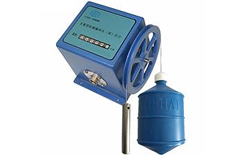
HSW Mechanical Display Float Type Water Level Gauge
Contact Info
- Add:Building 15, 1st Floor, Unit 15#02, Phase I of Liandong U Valley-Xuzhou Economic and Technological Development Zone Intelligent Manufacturing Park, Xuzhou Economic and Technological Development Zone, Zip:
- Contact: 高经理
- Tel:0516-87939789
- Email:2811207280@qq.com
Other Products


The HSW series float-type water level gauge is a digital water level sensor that integrates mechanical and electrical technologies. It converts the angular displacement of the output shaft into corresponding digital quantities, enabling high-precision measurement of the liquid level height and accurate position confirmation. It features a power-off memory function.
Its working principle is as follows: the water level sensor measuring wheel is installed on the input shaft of the encoder. One end of the steel wire rope is connected to the float, and the other end is connected to the counterweight. The steel wire rope is wound around the measuring wheel. When the liquid level changes, the float rises or falls with the liquid level, driving the measuring wheel to rotate, and the encoder outputs the corresponding real-time water level value.
This sensor has a reasonable structure, strong anti-interference ability, high resolution, large range, long service life, and a signal tracking memory function after power failure. It can be used for long-term liquid level measurement while ensuring stable and reliable performance.
It is widely applicable for water level measurement of surface water or groundwater in rivers, lakes, reservoirs, ship locks, hydropower stations, hydrological stations, water plants, and petrochemical industries.
II. Technical Parameters
1. Basic Parameters
A Measurement range: 0-5, 10, 20, 40, 80 meters as required;
Water level change rate: 100 cm/min
C Resolution: 1 cm
D Starting torque of the water level wheel: < 100 g·cm (0.0098 N·m)
E Measurement accuracy: ≤ ±2 cm or 0.2% F·S
F Display: Six-digit decimal mechanical counter
2. Mechanical Parameters
a Working circumference of the water level wheel: 32 cm
Measuring cable: Φ0.8 mm stainless steel cable
c Float diameter: 10 cm, 15 cm (optional or other custom sizes)
3. Electrical Parameters
Output form: Contact switching output; Contact resistance: ≤ 0.5 Ω; Insulation resistance: ≥ 10 MΩ
4. Communication Interface (Optional)
RS485 interface (MODBUS-RTU protocol);
Gray code output; 4-20 mA current analog output;
5. Operating Environment
a Ambient temperature: -25°C to 85°C
Relative humidity: < 95% (40°C)
C Dimensions: 132 × 132 × 115
d Reliability index: Under normal maintenance conditions, MTBF ≥ 25,000 hours
e Power supply voltage: 12-24VDC (not used for Gray code output)
III. Working Principle and Structure of the Float-Type Water Level Gauge
Instrument structure and working principle:
This instrument consists of a float, steel wire rope, counterweight, measuring wheel, sensor, bracket, output socket, and other components.
The working principle is as follows: The instrument uses the float to sense changes in water level. During operation, the float and counterweight are firmly connected to the steel wire rope, which is suspended in the "V"-shaped groove of the water level wheel. The counterweight tightens the steel wire rope and balances the system. Adjusting the float's ballast allows it to operate at the normal draft line. When the water level is constant, the forces on both sides of the float and counterweight are balanced. When the water level rises, the float generates upward buoyancy, causing the counterweight to pull the steel wire rope and rotate the water level wheel clockwise, increasing the sensor's display reading. When the water level falls, the float sinks, pulling the steel wire rope and rotating the water level wheel counterclockwise, decreasing the sensor's display reading.
In this series of instruments, the mechanical water level sensor's water level wheel has a measuring circumference of 32 cm, and the water level wheel is coaxially connected to the sensor. For each full rotation of the water level wheel, the sensor also rotates once, outputting 32 corresponding sets of digital codes. When the water level rises or falls, the sensor's shaft rotates by a certain angle, and the sensor synchronously outputs a corresponding set of digital codes (binary cyclic code, also known as Gray code). Instruments of different ranges can output 1,024 to 8,192 different codes, enabling measurement of water level variations from 10 to 80 meters.
The encoded signals can be transmitted via a multi-core cable connected to the instrument socket to an electronic display or computer in the observation room for monitoring, recording, or data processing. Water level gauges equipped with an RS485 digital communication interface can be directly connected to communication devices or computers, forming hydrological automatic monitoring and reporting systems or hydrological satellite telemetry systems.
The instrument's built-in RS485 digital communication interface (optional) features addressing and gating functions, enabling long-distance information transmission via a two-wire system. A single pair of twisted signal wires can drive or receive signals from up to 31 water level (or gate position) sensors, enabling remote monitoring networking.
Installation, Usage, and Precautions for Float-Type Water Level Gauges:
1. This sensor is a high-precision instrument. Avoid knocking, dropping, or colliding during installation.
2. Ensure correct wiring. Incorrect wiring may damage the internal circuit of the sensor.
3. Do not bundle the sensor's output wires with power lines or transmit them through the same conduit. Avoid using near distribution panels to prevent interference.
4. Use shielded or twisted-pair cables for power lines.
5. Fix the installation base plate above the measuring well, ensuring that the counterweight and float do not rub against the base plate when hanging naturally. The connection holes between the base plate and the water level gauge are 78*114 mm, with 4-ф4.5 mm holes, using M4*20 connecting screws.
6. Use two 150 mm diameter PVC pipes (or one pipe with a diameter of 200 mm or more) or steel pipes installed vertically side by side for the measuring well.
7. The measuring well should be installed vertically, and its inner wall should be as smooth as possible to avoid hindering the free movement of the float and counterweight. Ensure that the float and counterweight do not rub against the well wall.
8. Install a weatherproof box above the sensor.
| Industry Category | Others |
|---|---|
| Product Category | |
| Brand: | 徐州海河 |
| Spec: | HSW |
| Stock: | 10 |
| Manufacturer: | 徐州海河水文设备有限公司 |
| Origin: | 113203 |


