


Floating Oil Skimming Device Model LTFDC
Contact Info
- Add:洪湖市滨湖办事处工业开发区, Zip: 433200
- Contact: 文红霞
- Tel:0716-2263888
- Email:HHLTGS@163.COM
Other Products


The utility model discloses a floating oil outlet device, comprising an oil pipeline, a rotary joint, a floating disk connection device, a suction port, an oil outlet short pipe, and a fixed support. One end of the oil pipeline is connected to the rotary joint, and the other end is connected to the suction port. The suction port is connected to the floating disk connection device. The floating disk floats on the liquid surface, and the suction port is suspended below the liquid surface via the floating disk connection device. The rotary joint connects the oil pipeline to the oil outlet short pipe. The rotary joint is connected to the oil outlet short pipe at the bottom of the oil tank via a flange, and the oil outlet short pipe is mounted on the fixed support. When the flange diameter of the floating oil outlet device exceeds DN200, the rotary joint is replaced with a metal hose, which helps overcome mechanical failure issues. The utility model features a clever structural design, convenient oil extraction, effectively ensures that the discharged medium is relatively clean, effectively removes impurities, and is suitable for various vertical and horizontal oil storage tanks.
1. A floating oil outlet device, characterized by comprising an oil pipeline, a rotary joint, a suction port, a floating disk connection device, an oil outlet short pipe, and a fixed support. One end of the oil pipeline is connected to the rotary joint, and the other end is connected to the suction port. The suction port is connected to the floating disk connection device. The suction port is suspended below the liquid surface via the floating disk connection device, and the rotary joint connects the oil pipeline to the oil outlet short pipe.
2. The floating oil outlet device according to claim 1, characterized in that the rotary joint is connected to the oil outlet short pipe at the bottom of the oil tank via a flange.
3. The floating oil outlet device according to claim 1, characterized in that the oil outlet short pipe is mounted on the fixed support.
4. The floating oil outlet device according to claim 1, characterized in that the suction port is a bent pipe section, with the curved pipe mouth immersed in the liquid. The upper side of the pipe mouth is connected to the floating disk via the floating disk connection device, and the bent pipe body is sleeved onto the oil pipeline.
5. The floating oil outlet device according to claim 1, characterized in that the rotary joint is replaced with a metal hose.
Floating Oil Outlet Device
【Technical Field】
The utility model relates to the technical field of oil storage devices, in particular to a floating oil outlet device.
【Background Art】
In the process of national economic construction and production, in the construction of national defense, and in the process of oil extraction and refining, a large number of oil tanks of different specifications and purposes need to be constructed. Some of these tanks are solely used for oil storage, while others are used for oil production and processing. Regardless of the purpose and location of oil storage, all storage tanks are filled for the purpose of discharge.
However, during the process of discharging oil from tanks, the most common problem is the presence of water and mechanical impurities in the discharged medium. This has always been a concern in the field of oil and gas gathering and transportation, and no effective solution has been found yet.
【Utility Model Content】
In view of this, to overcome the shortcomings of the existing technology, the utility model provides a floating oil outlet device, which effectively solves the aforementioned drawbacks and ensures that the discharged medium is relatively clean, effectively removing impurities.
To achieve the above purpose, the technical solution of the utility model is as follows:
A floating oil outlet device comprises an oil pipeline, a rotary joint, a suction port, a floating disk connection device, an oil outlet short pipe, and a fixed support. One end of the oil pipeline is connected to the rotary joint, and the other end is connected to the suction port. The suction port is connected to the floating disk connection device, and the suction port is suspended below the liquid surface via the floating disk connection device. The rotary joint connects the oil pipeline to the oil outlet short pipe.
The floating disk connection device is connected to the floating disk at the top of the tank, and the floating disk floats on the liquid surface.
Preferably, the rotary joint is connected to the oil outlet short pipe at the bottom of the oil tank via a flange, and the oil outlet short pipe is mounted on the fixed support.
The suction port is a bent pipe section, with the curved pipe mouth immersed in the liquid. The upper side of the pipe mouth is connected to the floating disk via the floating disk connection device, and the bent pipe body is sleeved onto the oil pipeline, with fasteners used to secure the connection.
The rotary joint connects the oil pipeline to the oil outlet short pipe, allowing oil to flow through the oil pipeline into the oil outlet short pipe. The oil pipeline can swing with the rotary joint, facilitating oil extraction from different parts of the oil tank.
The oil outlet short pipe is connected to a tank wall connection pipe, and oil flows out of the tank through the tank wall connection pipe, achieving the purpose of floating oil extraction.
Multiple fixed supports are provided at the bottom of the oil tank to secure the oil outlet short pipe and support the oil pipeline. When the liquid level drops to the bottom, the fixed supports serve to support the oil pipeline body.
Furthermore, when the flange diameter of the floating oil outlet device exceeds DN200, the rotary joint is replaced with a metal hose, overcoming mechanical failure issues such as leakage and jamming that are prone to occur with rotary joints.
When the rotary joint is replaced with a metal hose, the floating disk can be replaced with a float. The float is connected to the suction port, and the suction port is suspended below the liquid surface via the float.
The working principle of the utility model is as follows: when the oil tank is filled or discharged, the floating oil outlet device moves up and down with the liquid level via the float or floating disk. Since the float or floating disk is connected to one end of the oil pipeline, and the other end of the oil pipeline is connected to the rotary joint or metal hose, the oil pipeline moves up and down driven by the float or floating disk. The end connected to the float or floating disk is the oil suction port, designed to be immersed as shallowly as possible below the liquid surface. Oil flows in from this port, passes through the oil pipeline to the other end, enters the rotary joint or metal hose, flows through the rotary joint or metal hose into the oil outlet short pipe, and then to the tank wall connection pipe before exiting the tank, thereby achieving the purpose of floating oil extraction and always extracting surface fuel. Due to the sedimentation of water and impurities under gravity, the water and impurity content in the upper fuel layer is always lower than that in the bottom oil layer. Therefore, using the floating oil outlet device to extract the upper medium ensures the discharge of a relatively clean medium and extends the service life of downstream purification equipment.
The beneficial effects of the utility model are its clever structural design, convenient oil extraction, effective assurance of a relatively clean discharged medium, effective removal of impurities, and suitability for various vertical and horizontal oil storage tanks.
【Description of Drawings】
To more clearly illustrate the technical solutions in the embodiments of the utility model or the prior art, the drawings required for describing the embodiments or the prior art will be briefly introduced below. Obviously, the drawings in the following description are only some embodiments of the utility model. For those skilled in the art, other drawings can be obtained based on these drawings without creative effort.
Figure 1 is a schematic structural diagram of the utility model.
Figure 2 is a schematic structural diagram of the utility model with a metal hose replacing the rotary joint.
In the figures: 1. oil pipeline, 2. metal hose, 3. oil outlet short pipe, 4. float, 5. suction port, 51. floating disk connection device, 6. fixed support, 7. floating disk, 8. rotary joint.
【Detailed Description】
The technical solutions in the embodiments of the utility model will be clearly and completely described below with reference to the accompanying drawings. Obviously, the described embodiments are only a part of the embodiments of the utility model, not all of them. Based on the embodiments of the utility model, all other embodiments obtained by those skilled in the art without creative effort shall fall within the protection scope of the utility model.
Referring to Figure 1, a floating oil outlet device comprises an oil pipeline 1, a rotary joint 8, a floating disk connection device 51, a suction port 5, an oil outlet short pipe 3, and a fixed support 6. One end of the oil pipeline 1 is connected to the rotary joint 8, and the other end is connected to the suction port 5. The suction port 5 is connected to the floating disk 7 via the floating disk connection device 51. The floating disk 7 floats on the liquid surface, and the suction port 5 is suspended below the liquid surface via the floating disk 7. The rotary joint 8 connects the oil pipeline 1 to the oil outlet short pipe 3. The floating disk 7 has a large area and provides significant buoyancy on the liquid surface.
The rotary joint 8 is connected to the oil outlet short pipe 3 at the bottom of the oil tank via a flange, and the oil outlet short pipe 3 is mounted on the fixed support 6. The suction port 5 is a bent pipe section, with the curved pipe mouth immersed in the liquid. The upper side of the pipe mouth is connected to the floating disk 7 via the floating disk connection device 51, and the bent pipe body is sleeved onto the oil pipeline 1, with fasteners used to secure the connection.
The floating disk 7 is a specialized device for internal floating roof tanks and external floating roof tanks, and the floating disk connection device 51 is used to connect the floating disk 7 to achieve the effect of up and down floating.
The rotary joint 8 connects the oil pipeline 1 to the oil outlet short pipe 3, allowing oil to flow through the oil pipeline 1 into the oil outlet short pipe 3. The oil pipeline 1 can swing with the rotary joint 8, facilitating oil extraction from different parts of the oil tank. The oil outlet short pipe 3 is connected to a tank wall connection pipe, and oil flows out of the tank through the tank wall connection pipe, achieving the purpose of floating oil extraction.
Multiple fixed supports 6 are provided at the bottom of the oil tank to support the oil pipeline 1 when the liquid level drops.
When the oil tank is filled or discharged, the floating oil outlet device moves up and down with the liquid level via the floating disk 7. Since the floating disk 7 is connected to one end of the oil pipeline 1, and the other end of the oil pipeline 1 is connected to the rotary joint 8, the oil pipeline 1 moves up and down driven by the floating disk 7. The end connected to the floating disk 7 is the oil suction port 5, designed to be immersed as shallowly as possible below the liquid surface. Oil flows in from this port, passes through the oil pipeline 1 to the other end, enters the rotary joint 8, flows through the rotary joint 8 into the oil outlet short pipe 3, and then to the tank wall connection pipe before exiting the tank, thereby achieving the purpose of floating oil extraction.
Referring to Figure 2, a floating oil outlet device comprises an oil pipeline 1, a metal hose 2, a floating disk connection device 51, a suction port 5, an oil outlet short pipe 3, and a fixed support 6. One end of the oil pipeline 1 is connected to the metal hose 2, and the other end is connected to the suction port 5. The suction port 5 is connected to the float 4 via the floating disk connection device 51. The float 4 floats on the liquid surface, and the suction port 5 is suspended below the liquid surface via the float 4. The metal hose 2 connects the oil pipeline 1 to the oil outlet short pipe 3.
When the flange diameter of the floating oil outlet device exceeds DN200, the rotary joint 8 is replaced with a metal hose 2, overcoming mechanical failure issues such as leakage and jamming that are prone to occur with rotary joints.
When the rotary joint 8 is replaced with a metal hose 2, the floating disk 7 is replaced with a float 4. The float 4 is connected to the suction port 5, and the suction port 5 is suspended below the liquid surface via the float 4.
Fixed supports 6 are provided below both the metal hose 2 and the oil pipeline 1 to support the entire floating oil outlet device.
When the oil tank is filled or discharged, the floating oil outlet device moves up and down with the liquid level via the float 4. Since the float 4 is connected to one end of the oil pipeline 1, and the other end of the oil pipeline 1 is connected to the metal hose 2, the oil pipeline 1 moves up and down driven by the float 4. The end connected to the float 4 is the oil suction port 5, designed to be immersed as shallowly as possible below the liquid surface. Oil flows in from this port, passes through the oil pipeline 1 to the other end, enters the metal hose 2, flows through the metal hose 2 into the oil outlet short pipe 3, and then to the tank wall connection pipe before exiting the tank, thereby achieving the purpose of floating oil extraction.
By improving the structure of the entire floating oil outlet device, the utility model achieves convenient oil extraction, effectively ensures that the discharged medium is relatively clean, effectively removes impurities, and is suitable for various vertical and horizontal oil storage tanks.
The above are only preferred embodiments of the utility model and are not intended to limit the utility model. Any modifications, equivalent replacements, improvements, etc., made within the spirit and principles of the utility model shall be included within the protection scope of the utility model.
Figure 1
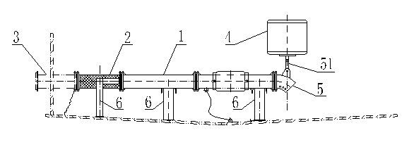
Figure 2
| Industry Category | Others |
|---|---|
| Product Category | |
| Brand: | 洪湖蓝天 |
| Spec: | DN50~300 |
| Stock: | |
| Origin: | China / Hubei / Jingzhoushi |


